LAB 2 (EI)
LAB 2 : ESP32 DIGITAL INPUTS & OUTPUTS
OBJECTIVES:
- To learn how to use GPIO port on the ESP32 controller to input and output digital value.
- Able to use ESP32 to read input like switch and touch sensor and show output value.
- Learn how to code using Arduino and print output.
EQUIPMENT & COMPONENTS:
- ESP23 DOIT DEVKIT V1 Board.
- 3.5mm LED
- 10k Ohm resistor.
- Push button
- Breadboard
- Jumper wires
- Potentiometer
INTRODUCTION:
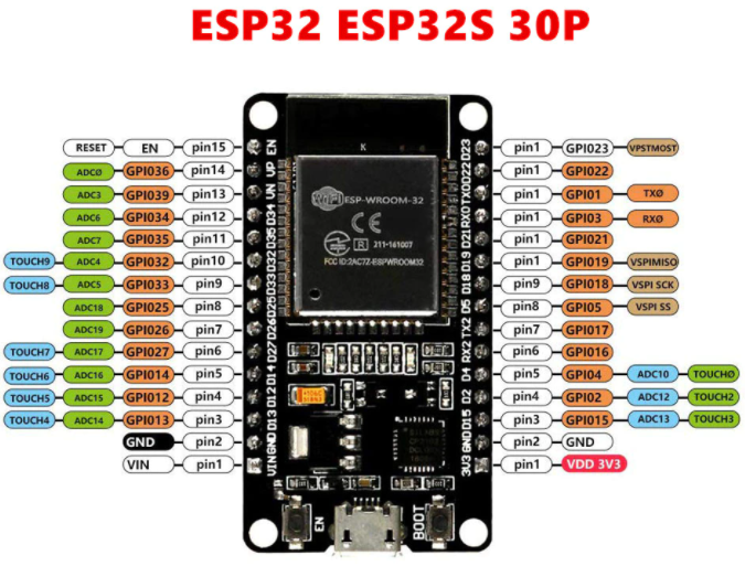
EPS32 is low power system on a chip microcontroller series featuring integrated Wi-Fi and dual-mode Bluetooth. The ESP32 series is powered by a Tensilica Xtensa LX6 dual-core or single-core microprocessor, a Tensilica Xtensa LX7 dual-core or single-core RISC-V microprocessor, and includes built in antenna switches, RF balun, power amplifier , low-noise receive amplifier , filters and power management modules. In this lab, we will learn how to utilise the Arduino ESP32 to construct a custom programmed application that can detect an output the value of an LED. We may required the objectives we want by connecting the pin of ESP32 to desired input or outpu devices and defining it in code. Figure below show the I/O pins on the ESP32 .
EXERCISE:
a)
1. Push button GPI04 to control a LED when toggel is on.
2. Copy code provided below to Arduino IDE.

3. First declare pin for LED output and switch input.
4. Set initial button state to LOW and create a "serial.begin" to check output.
5. Use If Else to control the LED to become HIGH when button is pressed(ACTIVE LOW).
OUTPUT:

b) ESP32 Touch Sensor
1. Reading the touch sensor is straightforward. In the Arduino IDE, we can use the touchRead ( ) fuunction, that accepts as argument, the GPIO we want to read.

OUTPUT:

- The LED turn on when pressed the connecting wire.
c) ESP32 Pulse-Width Modulation (PWM)
1. Firstly, choose the PWM channel. There are 16 channels from 0 to 15.
2. Then, set the signal's duty cycle resolution.
3. Next, specify to which GPIO the signal will appear upon.

OUTPUT:
1. To see the values changing, control the potentiometer by rotate it.
2. The maximum value we can get is 4095 and the minimum value is 0.


The port value is increasing when turning clockwise the potentiometer.
CONCLUSION:
To summarize, the ESP32 is a very intelligent and convenient microcontroller that can be readily programmed using software. Furthermore, the ESP32 may take input from a pin and output the value after it has been processed using the same pin. In this lab session, I learned how to programme an ESP32 with the Arduino software. The first step is to specify which pins will be used for input or output so that the ESP32 can recognize and perform its function. We may either transmit HIGH or LOW values to the LED light bulb at the same time, and we can also accept input values via a switch or sensor. In addition, I discovered that the touch sensor will produce a variable threshold value when in contact with various objects. PWM, on the other hand, is used to control the brightness of an LED light bulb by using a value between 0 and 255. (8bits). The higher the PWM, the brighter the LED light bulb. Finally, a potentiometer may be used as an input for the ESP32, and the user can spin it to control the input value. Many different types of smart applications may be constructed with this ESP32 microcontroller by employing an If Else or While loop
Comments
Post a Comment